Metal cutting for thick plate: Flame cutting without an alternative
If the cutting processes are classified according to the thickness of the plates, autogenous flame cutting comes first. These processes are used for unalloyed and low-alloy steels with a medium to large thickness. It is also popular because of its cost-effectiveness for plate thicknesses from 50 mm (2”) and up. For plate thicknesses above 250 mm (10”) thickness, there is currently no alternative cutting method.
In oxyfuel flame cutting, a flame heats the material on the surface until it reaches its ignition temperature (between 1150 and 1250 °C for mild steel). The metal burns due to the supply of oxygen. The heat of combustion in turn heats the underlying material to the ignition temperature. This allows the process to continue automatically (autogenously) into the depths. Unburned iron oxide becomes liquid and is blown out of the joint with the cutting oxygen. It can deposit as slag on the underside of the material.
7 success factors for efficient processes.
From automated warehouses to intelligently linked machines: find out which factors help to ensure efficient sheet metal processing.
Download: Success factors for efficient sheet metal processing
Metal cutting for thick plate: Flame cutting without an alternative
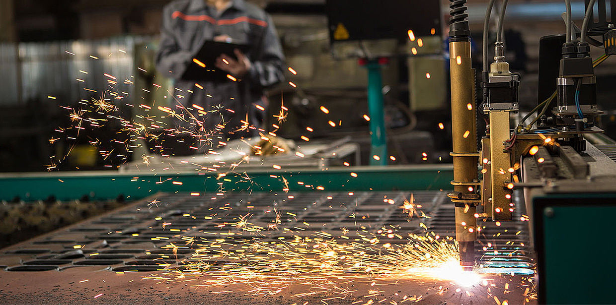
Because autogenous flame cutting works poorly or not at all with materials such as high-alloy steels, aluminum or copper, plasma fusion cutting (or plasma cutting for short) was developed. The process creates a thunderstorm in the sheet metal: In nature, a thunderstorm produces ozone (O3) as plasma gas when an arc discharges electrically. This can be smelled as "clean air" after a thunderstorm.
Plasma is an electrically conductive gas. Plasma cutting uses the heat content of the plasma to liquefy the material at a specific point. The high kinetic energy of the plasma gas volume flow then blows out the liquefied material.
The cut in metal is made by blowing out the kerf and feeding rate of the cutting head. The typical material thicknesses for plasma cutting are approximately between 0.5 and 160 mm (0.02” and 6.3”). Thanks to its high cutting speeds, the process has now also become established in areas of application previously reserved for flame cutting.
An overview of the most important leveling techniques
What are the different leveling techniques and how can new methods help to optimize the leveling process?
Cutting metal in large quantities: Stamping
If you want to use thinner sheet metal for cutting, stamping is an important process. It is used to produce flat parts or to introduce shapes and contours into a sheet. Stamped parts are manufactured industrially in a stamping machine with the help of stamping tools. The latter consists of two parts, the press and the die, which has an opening that matches the press. During the stamping process, the press moves linearly and dips into the die. The edges of the punch and die move past each other in parallel, separating the sheet.
In sheet metal forming, the result of the stamping process is not a continuous cut, even though it sometimes appears to be. Rather, the forces with which the stamping press presses on the material cut in the upper area. In the lower area, the material breaks as the punch exits the material.
There must be a cutting gap between the punch cutting edge and the insert breakthrough cutting edge. Its size depends on the strength and thickness of the material. Usually, the cutting gap reaches 2 to 5% of the material thickness. The cutting gap size then influences various factors, including the burr height on the cut part.
A special case of punching is so-called nibbling. In this process, a punching tool that is open on one side is used to line up many holes on a sheet edge. In contrast to conventional stamping and shearing, it allows a parting line and free shaping or a tool-independent cutting process. The tool can move in all directions and thus also create complex shapes.
Maximum flexibility with laser cutting
One advantage of stamping is that it can be used to efficiently produce many similar parts. However, the tooling costs have a negative effect on smaller series or individual pieces. For this reason, laser cutting has become well established in sheet metal processing. The laser beams used for this are made up of electromagnetic waves. The laser beam can heat up and ablate almost any material, which is called ablation in physics.
Strictly speaking, two processes occur simultaneously in the laser cutting process: First, the material at the cutting front absorbs the laser beam and heats up. Second, the blowing gas blows the ablated material out of the kerf, thereby also protecting the focusing optics from vapors and spatter. Depending on whether the material is removed from the kerf as a liquid, oxidation product or vapor, a distinction is made between laser beam fusion cutting, laser beam flame cutting and laser beam sublimation cutting. This also has consequences for the formation of burrs. In laser flame cutting, the cut edges also have an oxide layer after the process, which must be removed.
Laser cutting works up to a material thickness of about 40 mm (1.6”), with stainless steel up to about 50 mm (2”) and with aluminum up to 25 mm (1”). The latter material is difficult to cut, however, because it reflects much of the laser radiation and because its high thermal conductivity dissipates a lot of energy from the cutting gap. The same applies to copper.
Rather less common with sheet metal: waterjet cutting and milling
Waterjet cutting is more of a niche in sheet metal working. Here, a water jet with a pressure of 4000 bar (58,000 psi) and a speed of 900 m/s (177,000 ft/s) is used to cut the metal.
The material removal in this process is based on the high pressure that the jet causes on the surface of the material. The water jet only removes microscopic particles close to the surface. The outflowing water additionally causes shear forces, which also contribute to material removal.
The advantage of waterjet cutting is that it relies only on pressure and not on thermal energy. That is because the heat in processes such as oxyfuel, plasma or laser cutting can distort the workpieces.
Another metal cutting process that is uncommon in sheet metal fabrication is milling. The milling tool removes the material by rotating around its own axis at high speed. In the process, either the tool traverses the desired contour or the workpiece is moved. In the process, the milling tool removes chips from the blank to produce the shape.
As common as milling is in industrial manufacturing, it tends to be the exception in sheet metal fabrication for producing the contour. It is only found in aircraft construction and medical technology, and sometimes in the production of aluminum front panels.
As with all machining processes, burrs also occur during milling, which have to be removed.